R52 – Discontinued
R52 Empty (without modules)

R52 with E27 Modules Loaded (modules not included)

R52 with Modules Loaded (modules not included)

The E27 as well as other modules by API, BAE, Little Labs, and Speck Electronics are perfectly compatible in the R52 (modules not included)
Features
- Compatible with select 500 series modules
- Internal regulated power supply w/ phantom power
- Steel chassis construction
- Machine-milled (not stamped) faceplate
- Brite-dip anodized aluminum faceplate
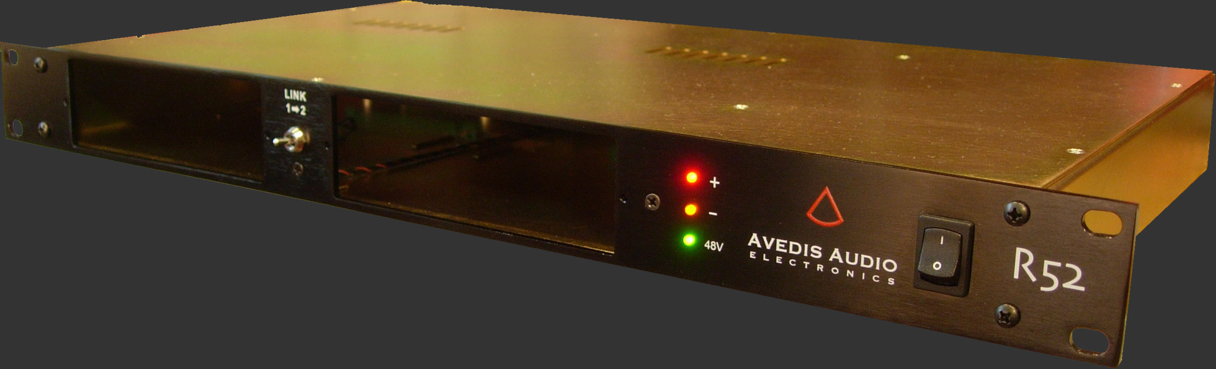
- LINK switch for connecting channels
- LED power supply indicator
- Grill cutout at top to aid module connection as well as guides at the bottom
- XSOLATE™ safely disconnects ground for isolation and quiet operation
- Come with shielded power cord

R52 2-Space 500 Series Module Rack Rackmount
Two R52 is a two-space 500 series power supply with link mode in a 19″ 1U rack-mount. The R52 is compatible with select 500 series modules.
FAQ
Why does the 48V light stay on when I have EQ‘s in it and don’t need phantom power?
The light stays on to let you know that the power is available and working properly whether or not you will use it. The 48V phantom power is on pin 15, a pin that goes nowhere in an equalizer. Only preamps use that pin.
If the 48V does dim after you put in an eq, or preamp for that matter, then turn off the R52 and remove the module. Then turn the R52 back on and if the light is back on again, then something is not right with the module.
One exception known: There were a small number of 560A/AT graphic eq’s, mostly from the 80’s, which used pin 15 for external gain. It is a good idea to cut this pin on the circuit board to prevent damage to the unit. Please contact API or a qualified tech to do this for you or if you have any questions, please ask.
I‘m planning on using 550A’s for this rack and heard of the inputs being unbalanced. What should I be aware of?
Modules 550, 550A, 550b, 553, and 525’s all have un-balanced inputs (whereas the 550A-1, 554, and 560’s are electronically balanced input). Read more here. This is usually not a problem when interfaced with something which has a transformer output, like a 312A or 512C mic-preamp. But electronically balanced outputs don’t usually like driving unbalanced inputs, and you may get a 6 db loss and/or some other frequency response, phase response, or headroom problems.
The best way to remedy this is to place Line input transformer before each equalizer. A good transformer will interface with both balanced and unbalanced gear, capable of handling high levels, and maintain excellent common-mode rejection. Good transformers are not inexpensive, but it is the best solution for the best sound.
A good quality 1:1 transformer that behaves well with an 18.5k ohm secondary (the input impedance of 550A/b) should do fine. One option and recommendation would be made by Jensen™ transformers in their PI-2XX if you are looking for an external transformer unit.
Another option is to have us mount Jensen™ transformers inside the R52, which was designed to accommodate this if needed. The extra cost would be $200.00 for this option. Please mention this when ordering. But adding the transformer to the input will only make the R52 for equalizers that are unbalanced and you cannot use your preamps. Also, phantom power will have to be disconnected in case someone does put in a preamp and accidentally engages phantom power, sending 48VDC through the secondary of the transformer.
What does the LINK switch do?
It simply “splits” the signal coming out of channel one into two directions – channel one output, and to channel two input.
The LINK switch, sometimes called a “patch” or “thru” by the Australians, allows Channel 1’s output to connect to Channel 2’s input without cutting Channel 1’s output, so you could record the 1 and 2 outputs independently. This is great if you have a preamp on Channel 1 and an equaliser or compressor on Channel 2 and want to record both signals at the same time. Once the Link is engaged, Channel 2’s input is disconnected.
What do the three LED’s tell me?
The LED’s are there to tell you about power supply status. If there is a problem with a voltage issue with a module, one or more of the LED’s will be off. Remember that you must turn the unit off before installing a module. After you are sure it’s secure, turn it on and look for all three LED’s to be on.
The last green LED is for phantom power. Sometimes the tie-lines or the patchbay in the studio can have a short in the cables and phantom will not work although the green LED may still be illuminated. Be sure to check for proper continuity and/or resistance on the cables, tie-lines and patchbays before engaging phantom power.
How do I link up two 525 compressors for stereo?
We could add a toggle switch to the back which simply connects Pin 6 together for newer 525’s. Older 525’s will need to have Pin 7 connected together through a 121Ω resistor, but only if repinning correctly since the 525 originally had a different pinout than the equalizers. There is another option to run them in quad, using lower resistor values.
I have some old BAE racked 312’s. Will they work with this rack?
Because these preamps were built using older cards, the ones with the input transformer part AP2622 is too tall to be properly plugged into the R52 because the top of it prevents the connectors to meet. If you must only use those preamps, we can lower the connector by lowering the mating connector, but let us know… and remember that it’s not something you want to change every week because you cannot plugin other standard sized modules.
How do you fit a 512C mic-pre?
The 512C’s tranformer has some rather bulgey wires that need to be pushed down and squeezed into the R52’s slot. Usually just a little squeeze will do it, but if you need, you can also remove the top cover while fitting it into the slot, just remember to have the R52’s power unplugged.
The price is about the same as a lunchbox or 6 space rackmount. Why?
In comparing the materials and labor with the R52 to other 6 space racks, there’s not much more in the manufacturing process to get more channels. But the R52 is not a lunchbox and it fills a different need. And manufacturing quality gear cannot be made cheaply.
Why not manufacture it overseas?
That may lower the price to the end user and like all cheap imitations, there will be a compromise in quality. While many electronic components are made in other countries, there’s no reason why everything else can’t be made and assembled here in the USA. We chose US made parts and electronic components whenever possible.
Would you not pay a little extra if you were told the quality and serviceability would be better?
Can I link up two eq’s and use it as a 6 band?
Yes, good idea. You can do things like cut 200Hz and boost 63Hz, or cut 12kHz while boosting 24kHz.
Can I connect two mic-pre’s together?
Not a good idea.
What will happen if I have a preamp on the second channel and I have phantom on and then Link it to channel one’s output?
Looking at the previous question, you shouldn’t do it in the first place, but if you did, and the preceding module is transformer-balanced output, then phantom would see the DC resistance of the output transformer’s secondary and as long as there is no resistive difference in relation to ground between the balanced outputs of the transformer, nothing should happen and no current will flow. But don’t do it anyway because it serves no purpose.