API, APSI, Aengus, Aphex Modules
API, APSI, Aengus, Aphex Modular Equalizers
Here is something I did to explain some of the features and history with API’s equalizers with quick facts and other details of my own. I’ve also included some info on Aengus and Aphex equalizers.
API 550
-3 band, 3 frequencies per band, 12 db boost/cut stepped discrete eq with LF and HF shelving on pushbutton
-FILTER switch for band-pass in 50-15khz.
-Two 2520 opamps, usually labeled Studio Systems Division or Farmingdale
-Proportional Q
-Unbalanced input, transformer balanced output
-Frequency knob was longer than the 550A and has a small black dot instead of a protruding pointer. Some 550’s had engraved numbers instead of the silkscreen.
-Gain strap on pin 11 could be used to adjusting for unity gain. Later models, like the 550A, 550b, and the 560’s also have this adjustment on pin 11, but it’s not featured on the 554.
All discrete design using two transistor (TIS prefix) voltage followers (VF) per band. The 2520’s were Studio System Division and/or Farmingdale types, which were the oldest. Sometimes 2.2M ohms resistors were found around the opamps, trace side, for stability. Red lamp indicator for IN, which would usually burn out and had it’s own voltage source from the 15 way connector. I would usually rewire this and put a LED with a voltage drop resistor.
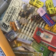
API 550A
-3 band, 5 frequencies per band, 12 db’s stepped boost/cut discrete eq with LF and HF shelving on pushbutton
-FILTER switch for band-pass in 50-15khz.
-Two 2520 opamps, usually labeled Mellville, Huntington, or Datatronix
-Unbalanced input (except modern reissue), transformer balanced output
-Frequency knobs shorter and had a pointer which came in both blue and clear.
All discrete, like the 550, but using three transistor VF per band. The 2520’s were Melville and Huntington types, and slightly improved over the older ones used in the 550. Additional frequencies per band, improved opamp stability, 47 ohm soldered on the trace side output, and LED indicator running off standard rails were other improvements over the 550. The 550A often had three ceramic capacitors on the trace side, which were put in there originally for improving stability – don’t remove them unless you think they need replacing.
In 1980, Kappa Systems Inc took over and licensed Datatronix to manufacture the API line who had been manufacturing the API line anyway by the late 70’s. At first, the same board layout as the old ones were used, but they had a green soldermask. After a short run of the green boards, Datatronix changed the circuit board design altogether but kept the electrical discrete design virtually the same. This time, the circuit board had traces on the top and bottom, making it a little more difficult to service, especially around the opamp traces; and the VF amps were on a separate smaller board which plugs into a socket.
The 550A was re-introducted by API in 2004 and made using the old style rotary switches and lots of wiring. But in 2007, a new 550A was introduced that, like the 550b, has PC mount rotary switches on adjacent circuit boards which facilitates easier assembly and makes use of surface mount, as well as, through-hole components. It also had some additional frequencies to each band. Unlike the unbalanced inputs of the vintage units, the new reissue 550A is also electronically balanced utilizing an LF411CN opamp to balance the input.

API 550A made in 2012
There is also a Saul Walker hand-wired version with a brushed aluminum faceplate.
API 550A-1
Same features as the 550A but made to be an economical version in the late 70’s. Key differences with the 550A are:
a) Electronically balanced input in contrast to the unbalanced input of previous three band eq’s. This alone makes some prefer using it when experiencing the 6 db drop when interfacing electronically balanced output to an unbalanced input.
b) Constant Q instead of the proportional Q of the 550A
c) Use of integrated circuits (IC)
d) Uses one 2520 opamp in the output stage – usually a Huntington
According to Al Davis, a designer at API, it should have been called a 551 but readily available old stock 550A faceplates were used instead. One way I can usually identify an A-1, without looking inside, is the rubbery feel of the rotary switches instead of the snap you feel with a 550A. 550A-1’s were sometimes found on ebay and sold as 550A’s by sellers who may or may not have known what it was because often the serial number sticker said “550A” without a mention of A-1, and sometimes there was no serial number sticker.
Looking at the inside, there is one 2520 driving the output transformer with a feed-forward design using a NPN transistor. The other amps are IC’s with an LF356 balancing the input and a TL074CN quad amp powering the bands and filter. The front rotary switches plugged into the circuit board with connectors.
Contrary to what internet loudmouths may say, the 550A-1 was not a bad module, it sounds very similar to a 550A with 2 or 4 db and becomes more noticable when pushed to 9 or 12 db, which is probably where most people would boost or cut if something was wrong. Overall, it was a good design with good noise performance and had the same headroom as any 550A due to the 2520 and output transformer in the output stage. It is not exactly a 550A with the Q difference and not quite as full in the low end, in my own tests, but still better than other eq designs of it’s time as the popularity of using IC throughout in the late 70’s became prevalent and overall quality diminished.
API 550b
4 band, 7 frequencies per band, 12 db’s stepped boost/cut, discrete with LF and HF shelving on toggle switches
Proportional Q
Unbalanced input
uses two 2520 opamps
A well designed and versatile extension to the 550A, but a little different in sound to the 550A due to small changes in the Q. The 2520 opamps were on sockets, making it easy to replace on the two, double-sided circuit boards. The input 2520 can only be replaced with a new type (from 1990 on) because they are a slight bit smaller than the old ones, which do not physically fit due to an adjacent circuit board . Later 550b’s used surface-mount VF amps.
API 553
-3 band, single frequency per band, 15 db’s boost/cut, discrete
-Unbalanced input
The 553 was available in the early to mid 70’s, and designed as a low cost module to be used in places where simple equalization was needed. High and Low frequencies were only shelving, and the mid was set at 3kHz, a frequency most sensitive to our hearing to help bring out the presence in music and dialogue. Very handy in broadcast and television for simple sound shaping.
The circuit used one 2520 opamp to drive the output transformer, but like the 550, 550A, and 550b, it had an unbalanced input. It also used two inductors for the low and mid frequencies. The 553 did not have a cover and care must be taken to prevent any damage to the wax-coated inductors.
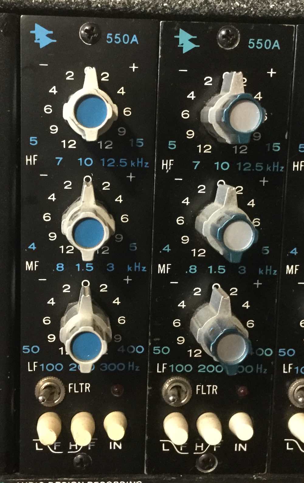
API 554
-3 band parametric with sweepable frequencies
Low- 30hz to 600hz
Mid- 200hz to 5khz
High- 800hz to 16khz
15 db’s of stepped boost or cut with a peak/shelf/bell selection toggle switch on the HF and LF, and peak/bell for the mid band
Electronically balanced input
From the mid-70’s, the 554 filled the need for a sweep-able frequency equalizer, instead of the set frequencies of other models, & is probably one of the more musical parametric EQ’s around. The peak selection is good for removing sibilance & narrow enough for notch filtering, and the bell is used for broader one octave bandwidth adjustments. The shelving selection can not only be used for boosting, but also a useful, sweep-able high or low pass filter.
The 554 uses dual IC opamps in a state-variable filter design found in many popular consoles with parametric EQ’s. There are two 2520 opamps, one being in the output stage driving the output transformer. The electronically balanced input uses a 741 type (MC1439, MC1741), and sometimes an LF series IC is found there even though it’s a JFET. The filter amps are 4558’s, which are like dual 741’s. Putting in something else, like high-speed JFET type opamps, may make the circuit unstable in certain areas. Because there are traces on the top and bottom of the circuit board, care must be taken in removing any components for replacement to prevent damage to the traces. Any damages must be followed by redundant wires in place of the traces.
A couple of variations of a similar design were also used in the 544P (not to be confused with the 544 input module for the 1604 console) and 954 Programmable Parametric Equalizer. The 544PM was a manual version.
APSI 559
-9 band Graphic EQ, -12 dB cut, +15dB boost Unbalanced Input
Manufactered by APSI (Audio Processing Systems, Inc.) and distributed by API (then called Automated Processes Inc.). Unlike the 560, the 559 had an unbalanced input. The filter amps used IC’s, but had it’s own potted output stage discrete amplifier and an output transformer. The boost/cut sliders were actually mechanically stepped level switch with the numerical reading on the front. The bandwidth, or Q, was tighter than the 560, giving it a more “notch-ey” sound. Like all the other API eq’s, it has good noise and headroom specifications that holds well with 600 ohm loads.
Aengus Graphic Equalizer
9 band Graphic EQ, -12 dB cut, +15 dB boost, Unbalanced Input
Like the APSI 559, the Aengus had stepped sliders with numerical readings and was also unbalanced on its input. Performance was good, and like other graphics, it had IC amps for every band and discrete output stage on a separate daughter-board. Output transformer was standard on all units. The unit did not come with a chassis cover so care must be taken not to twist and damage the board. And never spray harsh chemicals on any of the plastic parts to clean them, otherwise the chemical may attack the plastic and seize it’s mechanical function.
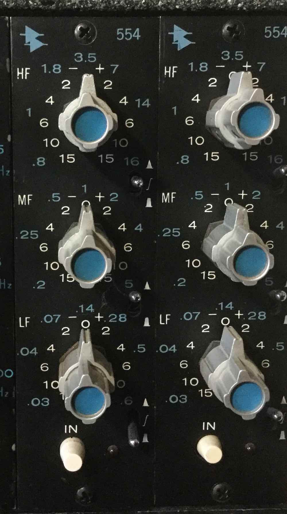
Aphex EQF-2
3 band Parametric Equalizer and Filter, Unbalanced Input, Optional transformer output
Introduced in 1981, this was a very versatile equalizer. It had a different way of using a pot where zero cut/boost was CCW position and turning clockwise would cut. If you wanted to boost, you would push a button designated as a “+”. This made it easy to find perfect reciprocals of boosting and cutting. There was a HP and LP Filter on two concentric pots in opposite directions and with a push of a button for selecting the filter, you can bring them in the other direction to use them. The Q on the filters was constant and not too tight unless you choose to tighten the Q with another eyelet pushbutton.
The EQF-2 has an unbalanced input as well as an unbalanced output when it was transformerless- not something preffered in professional interfacing of outboard gear. Most of the ones I’ve seen had no output transformer, but there is room for one and I would highly recommend putting one in. Integrated circuits (IC’s) are used throughout and gives this eq its parametric versatility. The output stage uses discrete transistors with good headroom and noise performance.
The faceplates can be a bit wide as mouting tolerances were not taken into account; therefore, if you places 3 of them next to each other in a rack, you’d have a tough time lining up the mounting screws. Easy but tricky to fix – you would have to carefully, and evenly, shave off thousands of an inch on either edge.
Before Aphex, the company had some involvement with B&B Audio in the late 70’s. B&B made opamps in the same footprint as the 2520 that had an IC input, a 5534 type on a socket, and discrete driver transistors. They worked well and many were used in some old API consoles when 2520’s were thought too expensive to be in areas not as critical.
API 560
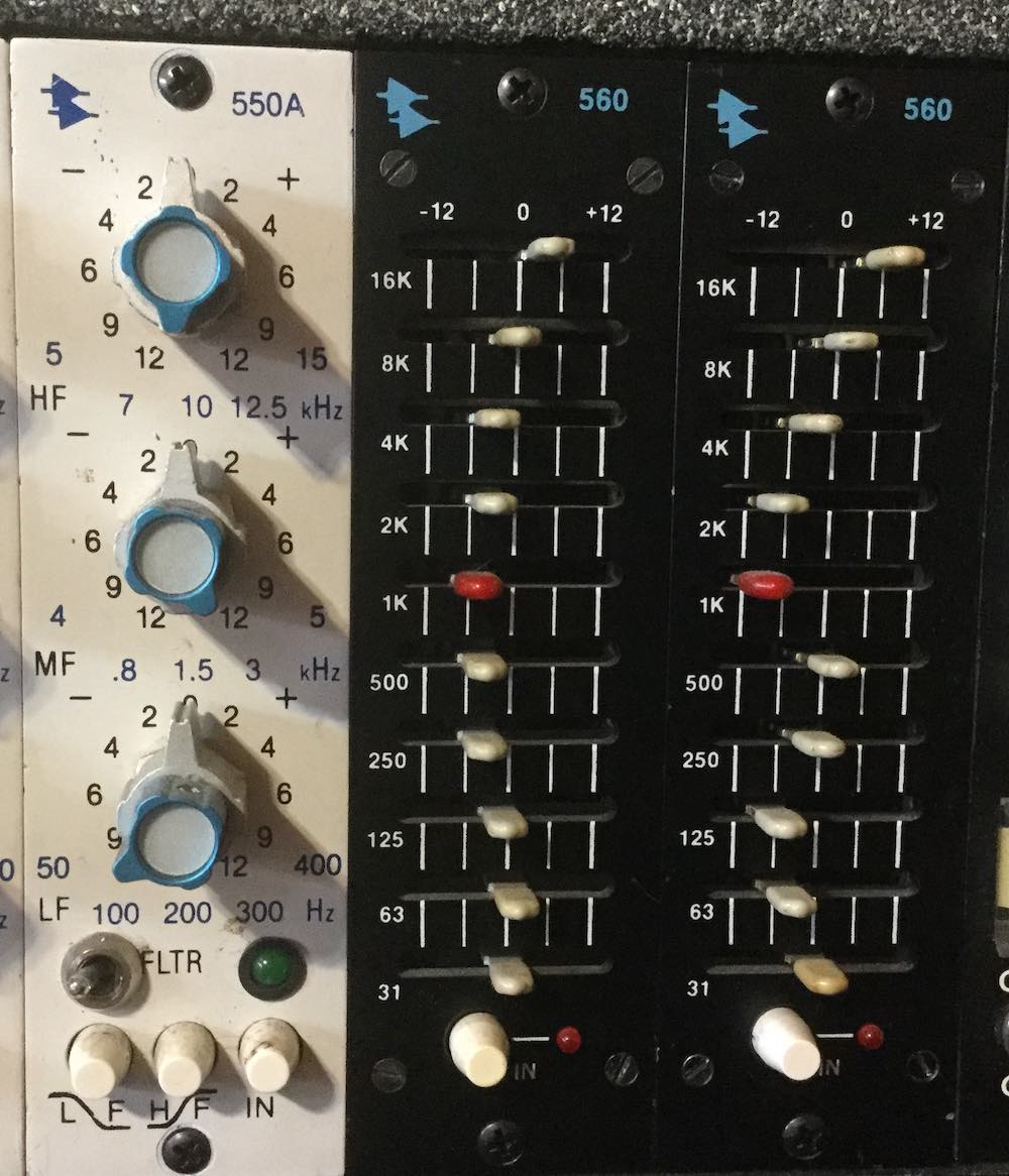
First release API 560
-10 band/octave Graphic Equalizer, 12db of boost/cut, Electronically balanced input
Like the 550A-1 and the 554, the input was differential (IC) balanced input which made it easy to interface with other gear, even if the source was unbalanced.
The first version, with no suffix, had a date codes on the components that would place production from the mid to late 1970’s. Amplifiers for each stage used socketed IC’s, using LF356’s and RC4558’s, but this model also had a single 2520 opamp in the output stage along with the AP2503 output transformer. The 560 came in an enclosed chassis and cover, whereas the later ones from the 80’s, and well into the 90’s did not have a cover.
The 560 was rare because in a console featuring 550A’s across the board, the typically four remaining slots were optional and not always filled with 560’s. Next to them, you would have a place for 525 compressor/limiters, but 525’s would only be wired for itself so you could not have an eq work in a 525 slot. More on 525’s someday…
All 560 models had good performance and sounded great since it was easy to slide the frequencies around which satisfied both our visual and aural senses.
API 560A & AT
The 1980’s model which had small changes to the slider values, but the biggest difference was – no 2520. Since only output drivers were needed to provide a low impedance output, the 2520 was replaced with two transistors, MPSU06 and MPSU56, which are hard to find today. The output transformer was optional and so the 560A was designated without it, and the 560AT came with the transformer. But the faceplates did not have A or AT written on them so you just have to look inside to know, but this shouldn’t be hard because these units did not come with covers like the 560 before it. I’ve done some modifications to these for adding the output transformer and replacing some resistor values to bring things back to unity.
Important Note – Some of these modules had a direct output on pin 15,
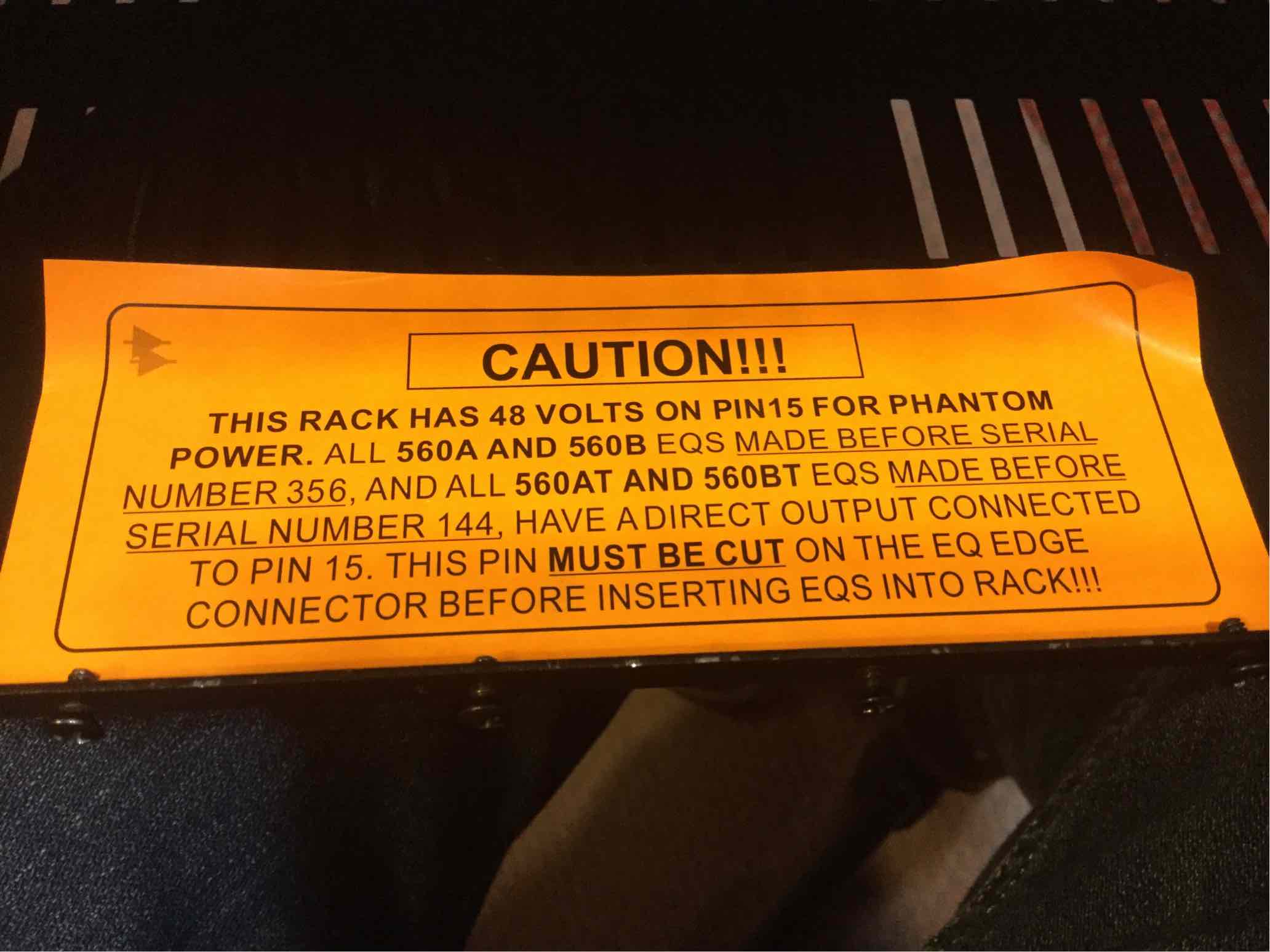
Warning label
which would be designated as the phantom power pin used by microphone preamplifiers in racks and this may cause damage to the unit from the 48V phantom voltage meeting the output of an amplifier or shorting through the primary of the transformer. API placed orange stickers on the inside of their lunchboxes stating that all 560A/B eq’s made before serial number 356, and all 560AT/BT units made before serial number 144, need to have this pin cut. If you have any of these modules, check if pin 15 is already cut off, which is normally done at the trace just inside the gold pin finger. If not, get someone who knows what to look for if you aren’t confident about doing it yourself – and please do a clean job.
API 560b
From 1987 on to present, these had the same overall design as the old, and the 2520 opamp was brought back in the output stage with a transformer, as well as the cover. Later units had surface mount IC but still had holes on the board for putting IC sockets if you needed to put a DIP-8 package. The 550bt was supposed to be the transformer output, and the 550b is the transformerless version but I have never seen a ‘b’ without transformers.
If you have old sliders on your old 560 that need to be replaced, that old part has been obsolete for a long time and you won’t find it anywhere. The only other option is to use new sliders but it will not fit on the old board the sliders solder to. You would need a new PC board to fit the new sliders but the new board does not mount on the old chassis. I had to deal with this issue and it was tough but I did manage to get my own pair of older 560’s fixed. Maybe a better solution with a custom made PC board would be available in the future.
API 560 ‘Re-issue’
I have not seen this yet in person. It is said to use a 2510 and 2520 amplifiers. The 2510 is a voltage op-amp likely used for an input stage, whereas the 2520 is a current opamp used for driving the output stage.
API 575
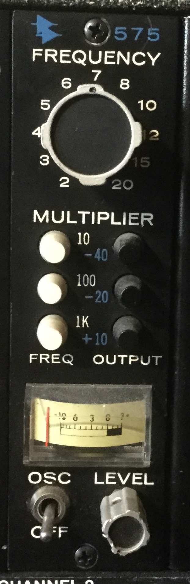
API 575 Oscillator
This is an oscillator, not an eq, so it doesn’t really belong on this list. And the 15 way connector is on the opposite end so it’s not the same as the other eq’s listed here and can’t plug into a standard rack… unless you used the last position in BAE’s 11 space which has a cutout for another connector to the right, but you’d have to keep that slot only for the 575.
Another thing… if you look at the 575 faceplate cutout, it’s really a 525 compressor faceplate – but upside down.
API 525
The 525 Compressor/Limiter was first designed in 1969 and had it’s own special place in the console and did not share the same pinout as the other equalizers like the 550. As a result, all older units must be re-pinned to allow for 500 series compatibility. Thankfully, the DC voltages are in the right place, but the audio inputs and outputs would need to be re-pinned and a few traces cut.
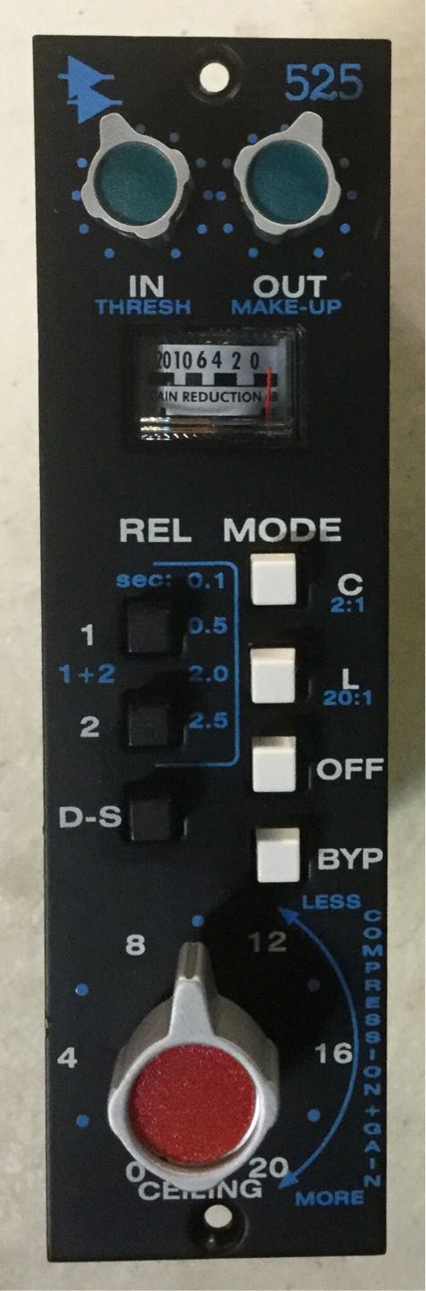
New 525
Like it’s equalizer cousins, the old 525 also had unbalanced inputs, with a transformer balanced output. It’s compression was done using a VCR, not to be confused with a VCA, which is just an early FET transistor. There are three 2520 op-amps – one for the VCR, another for the RMS controls which tells the VCR what to do, and one more for the output driver. Over time, the 525 went through some revisions and small improvements with suffixes B, C, and D where halfway through the meter was changed out for a smaller meter. The latest reissue 525’s have an electronically balanced input because interfacing with unbalanced could be problematic sometimes.
It featured up to 20dB’s of compressing or limiting in 2dB steps. The CEILING adjustment controlled both compress threshold and gain make-up to maintain a constant peak output level. The compress ratio is fixed at approximately 2:1, although it sounds like it is more, while the limiter ratio is 20:1.